Basic Properties obtained from Core Analyses
A solid understanding of geology, combined with core and log analyses form the basis of petrophysical interpretation A good discussion of integrating data is found in the Petroleum Engineering Handbook, Vol V(A), beginning on page 421. (see reference 1). Since the log data covers much more of the formation than the core, the core data may be used to improve or extend the log data.
Core analyses may be conducted on plug samples or the whole core. In carbonate reservoirs with a high degree of heterogeneity, whole core samples are preferred. Plug samples will provide only horizontal permeabilities.
Routine core analyses includes:
- Residual saturation of oil
- Porosity
- Gamma ray log -total and spectral
- Air permeability (whole core can be analyzed for vertical and horizontal permeabilities)
- Grain density
- Lithology description
At the completion of the routine core analyses, the core is normally slabbed and photographed. Some core samples may be retained for additional tests. All other analyses done on cores are considered special core analyses or SCAL. The most common SCAL are capillary pressure and relative permeability tests. Other SCAL tests include water susceptibility tests, wettability studies, rock compressibility, interfacial tention, cation ion exchange, mineral descriptions, formation resistivity factors, acoustic velocity and many thermal flood tests. The more common SCAL tests will be discussed in a separate section.
The core is normally cut with a diamond bit core barrel and the core is retrieved by pulling the barrel to the surface with the drilling string. Slips inside of the core barrel keep the core from falling out as it is pulled to the surface. Typical core barrels are 30 ft long, so selected intervals to core are a multiple of 30 ft. (see discussion at end on long core barrels) Cores cut are used in routine core analyses, and SCAL analyses are performed on selected samples. Generally-available core barrels outside diameter range from 5.75" to 7" and cut cores outside diameters range from 2" to 2.75."
The residual dead oil is normally reported in the core analyses. It can be a very low saturation and not representative of the residual oil from waterflooding. Extreme flushing from a core can take place as a result of jetting of drilling mud as the core is taken. Variables that influence the degree of flushing include: a) overbalance of pressure at the point where core is being cut, b) interfacial tension c) wettibility d) permeability e) core penetration rate f) core diameter g) type of drill bit h) drilling mud compositon. Further reduction in residual oil will occur as oil is expelled from core due to gas expansion. However, the residual oil saturations may help identify an oil-water contact. (Reference 1) Connate water saturation identification is possible if cored with an oil based mud, although the cores must be specially cut and preserved for this purpose.
Core barrels sometimes jam and can not take samples. This can occur in fractured carbonate formations, and can be taken of a good indicator of fractures. Often, all mobile oil is flushed from the cores by the drilling mud. Cores when taken to the surface may continue to bleed oil. This may be a qualitative sign of a tight oil bearing formation.
Coring in friable, uncemented and unconsolidated sands demands special coring, handling and analysis techniques so that the grain structure in not altered. (Reference 1) Core liners of fiberglass or aluminum help reduce friction. Cores should be cut as rapidly as possible and then slowly tripped to the surface. The inner core barrel may be cut into short sections and the ends plugged. Freezing the core before shipping is sometimes done.
Cores typically require cleaning prior to testing for air permeability to remove mud contamination. . In some cases, cleaning is insufficient and the permeability will still be affected. In whole core analyses, horizontal permeability is affected more, and unusually high K-vert/K-horiz ratios can result. In some cases, an outer layer of the core must be removed (trepanning the core), to obtain realistic values of permeability.
Core values of porosity are frequently compared with log values. (see Reference 1) The reported gamma ray from cores is used to aligning the core depths with log depths. The grain density may be used in the log analysis, particularly with dolomites which may have a grain density less than the textbook value of 2.87 gm/cc (this is based on personal experience). The porosity in cores may be higher than logs because they are not being subjected to overburden stresses. SCAL can identify the reduction of porosity and permeability in cores at varying levels of stress.
Coring in drilled wells
Cores are very desirable in new discoveries or initial delineation wells. However it is difficult to pick the best interval to core in the undrilled sections. Two options exists for taking cores in previously drilled but uncased wells- sidewall and sidetrack coring.
- Side wall coring (using gun)
Side-wall coring was introduced around 1940 for the purpose of obtaining information in previously drilled wells. In an open hole section, a wireline conveyed gun, that fires bullets into the formation. The core samples are caught in these bullets and the gun is reeled to the surface. The small samples are insufficient for assessing any rock property; they only serve to identify what fluids are present and for paleontological evidence. Also, sandstone samples are contaminated with drilling mud, so they are useless for direct permeability measurement. (Ref 1, page 88)
The advantage of side-wall cores is that they are inexpensive to run. They can be used in exploration wells to verify electric log interpretation of lithology. This coring is valid for slightly to medium unconsolidated sandstone rock types. (Ref 1, page 88). It is not recommended for most carbonates as the sampling is too sparce to identify permeability in the typical heterogeneous formations.
For sandstones, through microscopic examination, qualitative indicators of permeability (median grain size, sorting, degree of consolidation) are possible. An alternative to microscopic examination is to disaggregate the sample and use laser light scattering, which can then be correlated with permeability on the basis of whole core analyses. (Reference 1, page 88)
- Side wall rotary coring
- Side track coring
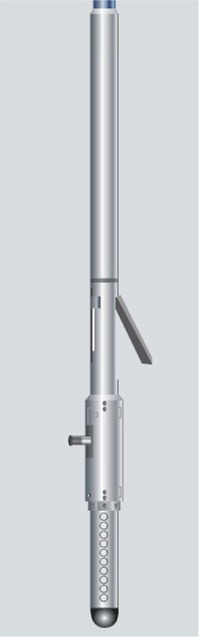
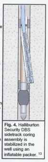
Side-track coring is new technology from Halliburton. With STC, the coring point can selected after the coring point has been penetrated, even after TD has been reached. The STC assembly is placed in the well just above the interval of interest so that the core to be cut accross the interval of interest is in a sidetrack to the original borehole. STC assembly is stabilized in place with an inflatable packer and contains a whipstock. A standard 4-1/8" slimhole wireline barrel/ bit is attached to the top of the STC assembly. Coring takes place as a sidetracked hole. Tool schematic is shown at bottom.
Specialized core barrels
The diamond bit cores will generally be taken in overpressured conditions and will have mud contamination. If conditions permit underbalanced drilling, the cores should be much less flushed with drilling mud. However, the core will not be preserved as the oil will be expelled by gas expansion as the core is taken to the surface. Pressure coring
- Pressure coring
The pressurized barrel prevents the core sample from bleeding until it reaches the laboratory where the release of fluids can be controlled and analyzed. The barrel contains a nitrogen gas reservoir (see diagram to right), which is filled with a specified pressure and a regulator set and tested to determine if it will operate at the required downhole pressure.
To come out of the hole, the core barrel is lifted several feet off bottom to separate the core and the formation and allow the outer barrel to drop. A ball bearing is then dropped into the drill pipe and pumped down to the top of the drill pipe. The ball serves two functions: (1) It allows the outer barrel to fall by its own weight which seals the upper sleeve valve (2) It activates the regulator to maintain the specified inner barrel pressure using the nitrogen reservoir.
After being cut, the sealed core is brought to surface under formation pressure, then frozen and preserved in dry ice. While still frozen, the inner barrel is removed and the core cut in sections for analyses.
- Sponge Coring
The sponge core barrel is a modification of a conventional barrel. With this system, oil-wet polyurethane liner is placed inside the inner barrel to absorb any oil that bleeds from the core as the core barrel is removed from the hole.
Prior to going into the hole, the six 5-ft sections of sponge liner are placed in the inner barrel and sealed. To eliminate the possibility of producing a filter cake between the core and sponge liner, the sponge is first evacuated and then pressurized with water up to 1,600 psi. This pressure is maintained as the core barrel goes intor the well. Once the sponge core barrels has been run in the hole, coring procedures are the same as with conventional coring.
Sponge coring can be used to obtain a residual oil saturation profile, invaluable in the design and monitoring EOR processes such as carbon dioxide flooding.
- Rubber Sleeve Coring
The rubber sleeve core barrel was developed to do a better job of recovering samples from unconsolidated and fractured formations. The tool has an additional chamber within the iner barrel in which 20 ft of tough, thin rubber sleeve is stored. A system of ratchets allows the rubber sleeve to jacket the core duing the operation. After 2 ft of core is cut, drill pipe must be lifted to adjust ratchets for further cutting. In all, 20 ft of ruber sleeve core can be cut in 2 ft increments. Tool complexity and the difficulty of coring unconsolidated and fracture formations are particularly challenging.
|
Side wall rotary coring tool |
Sidetrack coring assembly |
Unconsolidated Formation coring
One of the most difficult type of formations to core is unconsolidated formations. As a result of the damage during coring and transport, the excessive grain movement may sufficiently to damage cores to the point that laboratory restoration is impossible. Properties most sensitive to these properties are velocity, compressibility, and rock mechanics.
Success in this area relies on a coordinated plan from wellsite to laboratory, with the understanding that any error at any point can result in loss of obtain valuable information. In this case, the rubber sleeve core barrel is an option.
:Some of the keys to success as discussed in Reference 3 are: a) Trip out at a calculated rate that allows for gas expansion, particularly important for the last few stands of pipe b) Freezing all cores using dry ice and maintaining them in cryogenic freezers (at temperatures well below electric freezer temperatures) c) In the lab, cutting cores with a high-quality milling machine that minimizes vibrations and d) Cutting plugs using a drill bit cooled with liquid nitrogen. Plugs should be tested for porosity using a stress cell, designed for quick loading so samples due not thaw until under stress.
For water saturated shales where freezing could cause mechanical damage, even more damage occurred to cores that were not preserved with dry ice. (Reference 3) Alternatively, cores can be preserved with gypsum, however this results in massive damage throughout cores, making plugs unusable for analyses.
Other options/ advances
a) Low Invasion core heads: Standard coring can be done with three low invasion core heads: (1) PDC (polycrystalline diamond compact) core heads, suitable for softer formation, (2) thermally stable polycrystalline core heads, suitable for medium to hard formations, and (3) full diamond impregnated core heads, suitable for hard formations.
b) Specialized tools for core handling, logging and cutting: Once the core is brought to the rig floor, it must be handled with care. Hydraulic shear clamps are designed to prevent damage while breaking connections. On site, a portable gamma logger provides GR logs, which allows for rapid decisions on further coring and testing. An on site plug taker cuts sample plugs to ship to the laboratory.
c) Wireline conveyed core barrels: Coring is expensive in terms of rig cost as the drill string must be run in the hole and out again. . Wire line coring provides significant rig time savings by recovering the cores without tripping the whole drill string.
d) Specialized core barrels for oriented Cores: Oriented cores provide additional information on the anisotropic permeabilities trends, useful in reservoir management and water flood pattern programs.
e) Slim hole coring: Slim holes are drilled to perform evaluation of formation at a minimal cost. Specialized core barrels are available for these wells.
f) High pressure/ temperature and long core barrels: Long core barrels and/or high pressure formations result in gas release as the core barrel is tripped out of the hole. The standardization of 30 ft core barrels was due to concerns of gas release. However, venting of gas is possible with the "pressure relief check valve" which can safely vent the gas as the core is tripped out of the hole and also prevent the drilling fluid from entering the inner tubing. The use of the relief valve permits long cores to be taken, up to 600 ft. This has obvious application in drilling high inclination or horizontal wells.
g) Hard rock micro-coring: It has been recently reported that a new drill bit, the micro-coring bit (MCB), for hard rock drilling (>40,000 psi compressive strength) which retreives rock fragments, suitable for mineralogy examination. The micro-core is generated in the center of the bit. It has been reported that the "no center bit" improves the rate of penetration in addition to providing rock fragments, instead of pulverized rock ("rock powder"). See reference 5.
References:
1. Holstein, E.D, Reservoir Engineering and Petrophysics, Volume V, See discussion beginning on page V-83 (Chapt 3A, Petrophysics) for fluid saturations in cores, by E.C. Thomas, and the discussion beginning on page V-421 (Chapt 3H, Petrophysical Applications, by H. R. Warner and R. Woodhouse.
2. Swift, T. E., Kumar, R., Goodrich, J., and McCoy, R.L., "Pressure Coring Provides Innovative Approach", Petroleum Engineering International, August 1981.
3. Rosen, R., "Proper Core Analysis Yields Value", Petroleum Engineering International, October 1, 2008.
4. Baker-Hughes website, www.bakerhughesdirect.com, Overview- High Temperature High Pressure Coring
5. Deschamps, B., Desmette, S. and Birch, R., "Generate Micro-cores of Formations While Drilling", February 19, 2008.